This page is brought to you through the inspiration of Tom Rose and
his LED Display/Mod.
Tom's Original
Instructions
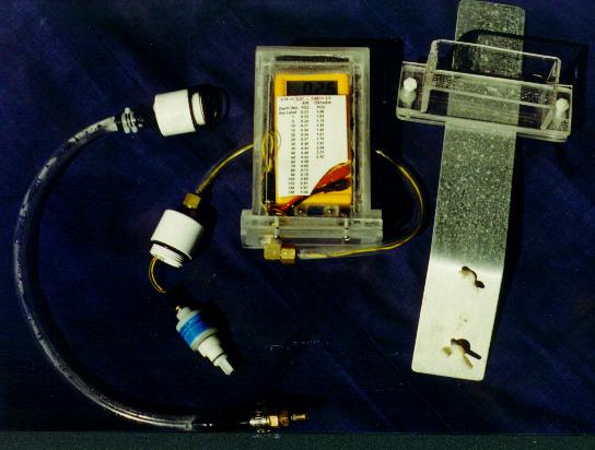
In the beginning there was a R17 Med, a 10K resistor, a $4.97 Harbor Freight Volt/Ohm meter and a home made acrylic case.
I read the raw millivolt output of the sensor.
Advantage: Few moving parts. (And they
did move when you shook the case.)
Disadvantage: Had to do math in your head during the dive.
Required some thinking on the part of the diver.
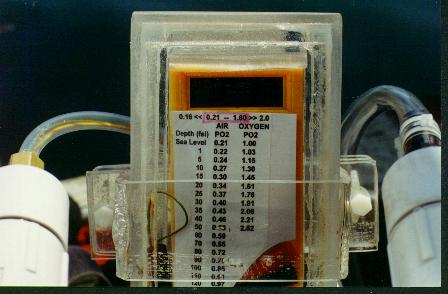
A simple graph to convert the millivolt to PPO2 was made after obtaining some initial readings.
Of course Max and Min numbers were all that was necessary to know for
"safety".
This unit was first seen used on "Bones".
My first mixed gas manual closed circuit rebreather.
Then a voltage splitter replaced the 10K resistor
on the sensor, and the output from the wiper was read on the HF Volt/Ohm
meter. The "pot" was "adjusted" such that the millivoltage "displayed"
could be interpreted as PPO2.
(A magic marker was used to place a big "decimal" point where I wanted
it.)
Advantage: Not many more moving
parts. Rubber cement cut down on the rattling.
Disadvantage: Had to "Believe" that the millivolt displayed
"Really is your PPO2".
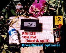
Than a more compact LCD panel meter was used.
See the breadboard picture above.
This was more compact, but did not have the benefit of a "back lit
display" and was difficult to read in poor visibility diving conditions.
Advantage: More compact in size.
Disadvantage: Not Backlighted, harder to read.
Some other circuits were played with, but that is another story.
Well now Tom Rose comes along and shares with us
a nice solution for a one battery lighted display.
Tom's Original
Instructions for the display is presented as noted.
What follows is
how easy one homebuilder on the west coast found to
make it.
And eventually make it work.
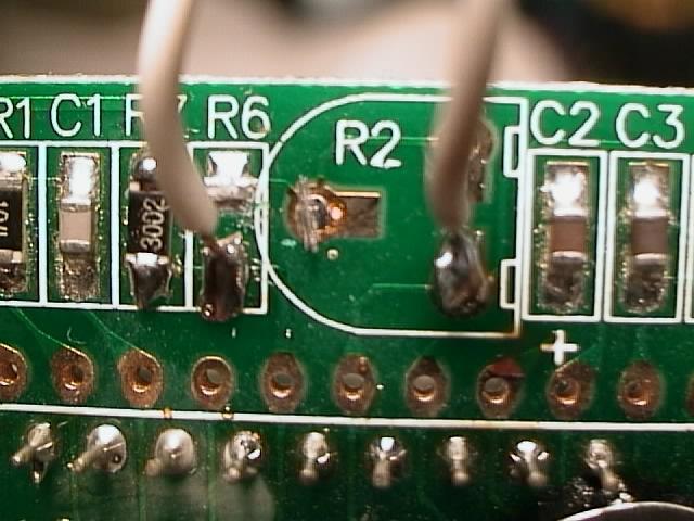
This solder joint at R6 was my main problem. I ruined the first
board somehow with the soldering iron or brute force.
The R6 and R2 leads goes to the 10K trim pot as per Tom Rose's advice.
Thank you Tom.
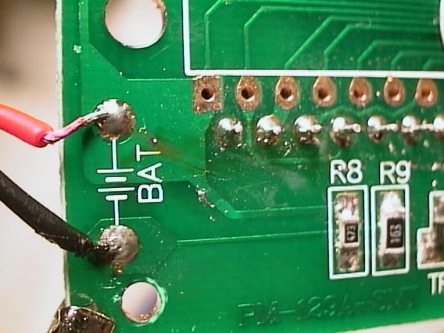
Battery leads: Red to (+), Black to (-)
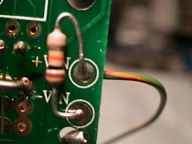
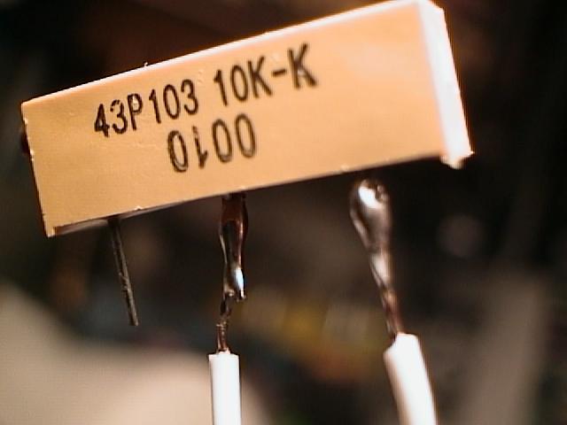
I placed the 10K resistor (required for this sensor) on the back of
the board, and connected the sensor leads on the front (other) side.
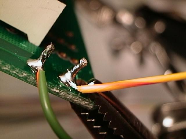
Sensor lead connected to front of board. Actually the extension
of the 10K resistor leads.
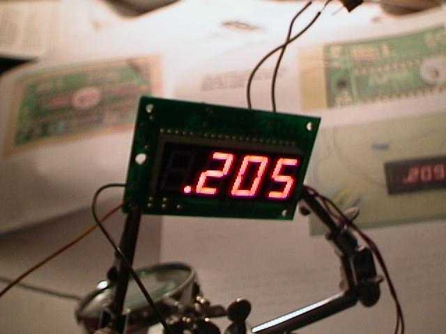
It's alive.
I adjusted the display to read what is shown by adjusting the 10K trim
pot shown above.
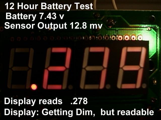
Note: Not only was the display Dim and read in Error (greater reading),
but it actually did not read at all.
The numbers were frozen on the display, and did not indicate any changes
with the changing millivolt output of the sensor .
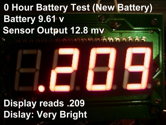
Tom told me that what happens is the reference voltage to the
AD converter goes down and makes the reading go up (when the battery dies),
and the last step in the battery life is that only the decimal point glows,
At this point, you should be snug in bed or in the bar.
Check your batteries !
Know how your electronics work, and all the ways they can lie to you.
Check how your electronics react to low battery voltage.
Check the operation of your unit constantly.
Enjoy,
Dr. Bob, Director
Crestline Experimental Dive Unit